Menu Close

MEASUREMENTS, CONTROLLING AND ADJUSTMENTS AT BOILER STRUCTURES IN POWER PLANTS AND COMBINED HEAT & POWER PLANTS

The latest position in our portfolio is the service on determining the forces and adjusting the suspension rods at boiler units in power and combined heat & power plants. Currently, high-power boilers are built based on a special requirements of the investor. In most cases, these structures are designed as suspended, as shown in the figure, where the weight of the boiler is transferred through a system of suspension rods (item 1) fixed to the boiler (item 2) by its cylindrical chambers or panels of sheet piling and a steel structure (item 3), supported on poles (item 4), and these transfer forces to the foundation. The location of suspension may change above or below the centre of gravity of the boiler, thus creating a structure suspended on the steel structure grate, half suspended or supported. Halfsuspension design boilers require a reduction in the number of suspension rods assembled only at the corners of the boiler, which in turn requires a more precise method of determining the forces in rods, in order to correctly determine the diameter and material.
The forces in the rods have so far been measured using simplified methods. After long-term operation of the boiler, a change in the forces in the rods is observed, which leads to uneven loading of the sheet piling. The figure below shows the distribution of forces in rods during the shutdown of the furnace chamber after 15 years of operation (with maintenance shutdowns). There is a parabolic force distribution on the rear wall of the chamber, which indicates the strong effort of the rods in the middle section. On the side walls and the front wall, loose rods in relation to the others may be observed. The presented distribution of forces is disadvantageous for the operation of the boiler sheet piling and may result in a shorter operation time of the furnace chamber and devices connected to it (back legs, compensators, pipelines or guides).

Particular risk is associated with overloading the rods which causes their yielding. Lack of control over the phenomenon of creeping material from which the rods are made may result in serious failures affecting the safety of operator’s work. This can lead to a situation in which the incorrect way of suspending the boiler elements, e.g. a steam super-heater as well as the lack of monitoring of forces in the rods, becomes one of the causes of damage to the suspensions. 

A steam super-heater diagram: (0) – suspension rods, (1) – cooler, 2 – second flag surface inlet manifold, (3) – third flag surface outlet manifold, (4) – fourth flag surface inlet chamber, (5) – rigid steel structure beams, (6a) – the second flag surface, (6b) – the third flag surface, (7) – fixing the flag surfaces to the tight walls of the boiler chamber.

The photo above shows a fragment of a damaged steam super-heater, after breaking the suspension rods. The aspects of safety, lifetime, reliability and repair costs which are related to the operation of boilers and possible failures, encourage boiler designers and users to take a comprehensive approach to the subject of regulation, monitoring and methods of determining forces in suspension rods.

Have a look at the new innovative method of determining forces in
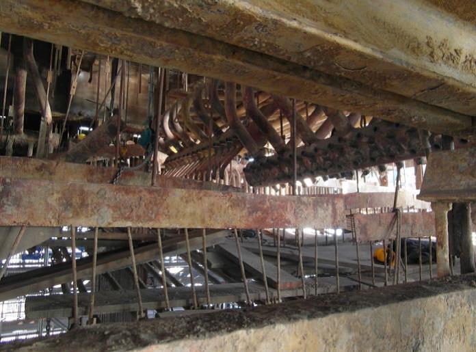
suspension rods of hanging boilers. The main reason of an inaccuracy in the measurement of force in the rods, in the
method currently used on the market, is the difficulty in determining the moment
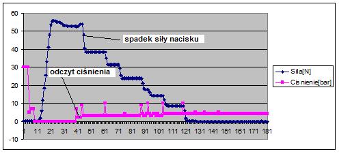
when the nut is being loosened – the photo below. Even a slight lift of the nut causes
a sudden increase in force in the rod. Measurement errors with the traditional
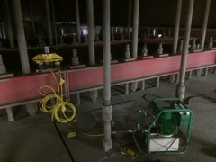
method are additionally increased due to the difficult environmental conditions
prevailing on the boiler – dust, temperature fluctuations, sometimes limited
visibility or insufficient lighting and difficulties in access to rods. The accuracy of
the measurement also depends on the experience of a person performing the
measurement.
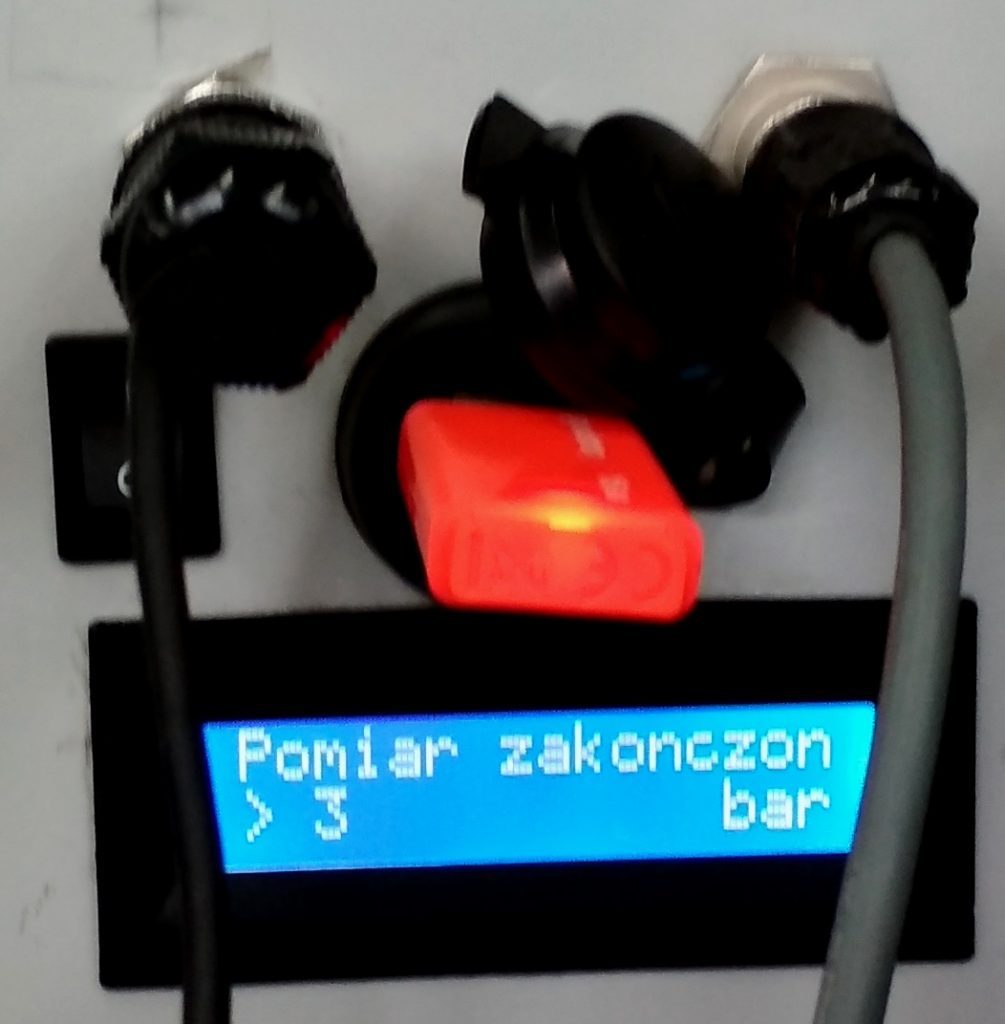
The EDA company offers measurements with the innovative method, using a
compact and mobile device for measuring forces in rods supporting the
structure of a power boiler – portable measuring device ED-SR-PMD-A01.
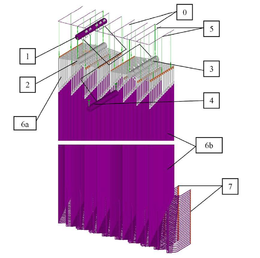
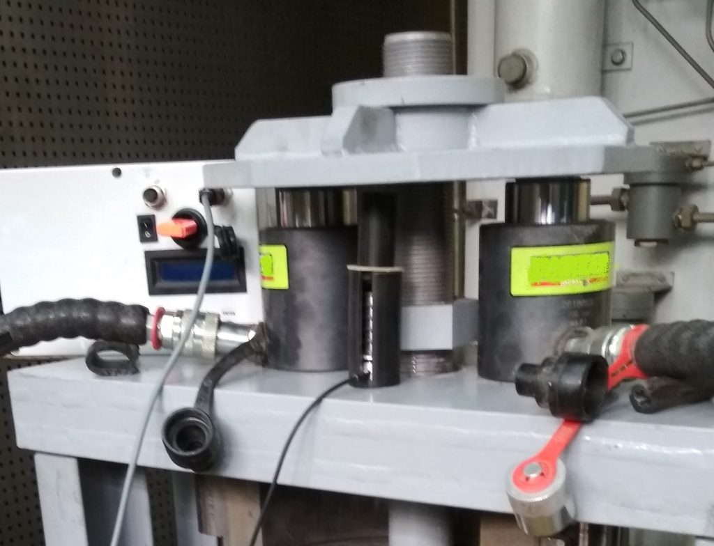
In order to improve the measurement accuracy, a pressure force control module (3) built in the device is used, which is attached between the surfaces (1) and (2), as
shown in the photo below. The device enables the automatic determination of the moment when the nut is being loosened.

⦁ Despite various boiler designs in power units and the resulting large variety of rod dimensions (different diameters, distances from the nut to the end of the rod), the device ensures easy installation and linear operation characteristics.
⦁ The measurement range of the device is from 0 to 400 [kN].
⦁ The device and its accessories and tools enable the measurement and adjustment of rods with a thread from M39 to M150 as well as inch and other threads from an adequate size range.
⦁ The system is equipped with a mobile recorder, with the possibility of rapid data copying to an external drive.
⦁ The device is resistant to dust and operation at high temperatures, up to 60 [°C].
⦁ Smooth operation of the pump and valves is ensured by pressure and temperature sensors coupled with the control system.

Above – values of thrust force and pressure as a function of time during the measurement Comparison of the innovative method with the traditional method of measuring the bars of a power boiler
The average value of the force in the rod determined using the traditional method was 132.8 [kN]. When using the Device for measuring forces in bars – Portable measuring device ED-SR-PMD-A01, the average value of the force was 105.5 [kN]. This is due to the fact in the traditional method the nut has already been slightly lifted. The difference in the determined mean values of the forces was 27.3 [kN]. The relative measurement bias was 25.9%. More than seven times greater deviation of the force values measured with the traditional method, compared to the method offered by EDA, confirms a significant improvement in the accuracy of the measurement with the new method. Moreover, apart from the accuracy, a significant advantage of the new measurement and regulation method is that the work is much less time-consuming – the new method enables the measurement and adjustment of a set of rods in a boiler block by up to two weeks shorter than the traditional technologies used so far.